
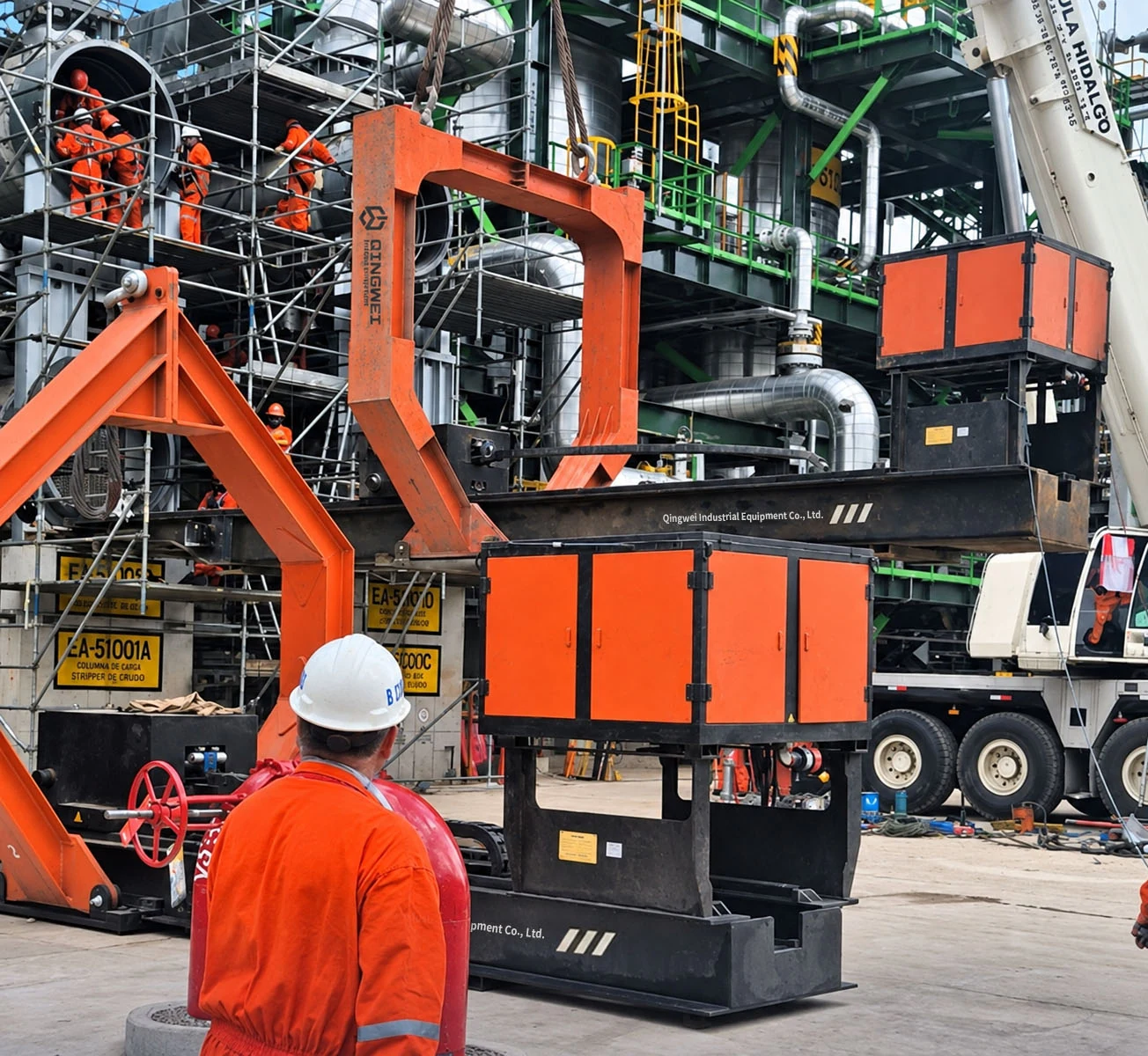
A tube bundle extractor can meet the required load rating and still need changes before it fits a particular heat exchanger. The difference often appears in the general arrangement drawing: where a dimension starts, which components are installed, and how much clearance remains around the bundle.
A general arrangement (GA) drawing shows the equipment layout and its principal dimensions. For a tube bundle extractor, also called a bundle puller, it helps buyers and maintenance teams check the proposed machine against the exchanger and the worksite. Read it together with the technical data sheet and the relevant exchanger drawing.
Start with the Drawing Revision and Reference Points
Check the model designation, drawing number, revision, units and approval status before comparing dimensions. Establish whether the drawing shows the base machine, an extended working configuration or the arrangement for transport.
Then follow the extension lines at both ends of each dimension. A length measured from the exchanger connection face describes something different from one measured between the outermost points of the machine. Use the stated dimensions; do not measure a screenshot or assume that an unlabelled sketch is to scale.
Keep the Main Dimensions Separate
The following terms answer different questions. If a value is missing from the GA, request a marked drawing or supporting technical schedule.
| Drawing term | What to establish | Why it matters |
|---|---|---|
| Maximum bundle length | Permitted bundle length for the stated configuration | Confirms the required bundle can be handled |
| Overall machine length | End-to-end length of the machine as shown | Defines the physical equipment footprint |
| Usable travel | Available movement of the pulling mechanism | Helps verify the complete extraction sequence |
| Maximum outside diameter | Actual bundle and tubesheet dimensions | Identifies the parts that must clear the equipment |
| Clear opening | Unobstructed space inside the fitted frame | Checks interference along the movement path |
| Centerline elevation | Axis height from a stated site datum | Locates the exchanger and extraction axis |
| Transport dimensions | Packed or dismantled length, width and height | Supports shipping and site access planning |
Read Bundle Length and Machine Length Independently
The maximum bundle length is an application limit. Overall machine length describes the equipment itself. A 9,000 mm overall dimension on a GA does not, by itself, establish a 9,000 mm bundle capability. Space occupied by the connection assembly, pulling mechanism and other components must be considered in the actual design.
Also check how the exchanger drawing defines bundle length. Tube length, tubesheet-to-tubesheet distance and the overall removable assembly may have different endpoints. Ask the supplier to identify the exact dimension used for the proposed extractor configuration.
When reviewing a model such as the BE45 diesel tube bundle extractor, match the project GA to the quoted working length and attachments. A model family name alone does not identify every possible arrangement.
For an extended machine, request separate confirmation of the base arrangement and the arrangement with the specified extensions installed. Clarify which end is called front and which is called rear. Adding an extension does not automatically increase usable travel or permitted bundle length by the same amount; the support arrangement and movement sequence also need review. Our guide to front and rear extension configurations explains their application.
Compare Bundle Diameter with the Actual Clear Opening
A diameter marked on the exchanger drawing may refer to the shell, tube bundle or tubesheet. These values are not interchangeable. Identify the largest part of the removable assembly that must pass through or alongside the extractor structure, including any projecting features.
On the extractor GA, distinguish the outside width of the lifting frame from the clear opening inside it. An outside dimension includes the structure and cannot be used as the available passage width. Review the opening with the supports, guards and other relevant components in their operating positions.
A headline maximum diameter is therefore a starting point for the review. Actual compatibility depends on the shape of the opening, the support position and the path taken by the bundle. Check the exchanger flange and tubesheet connection details as well, including any dimensions required for the specified clamps or pulling attachments.
Place the Extractor on the Site Layout
The equipment GA describes the machine. The site layout establishes where it can work. Use the exchanger extraction face and a clearly defined elevation datum to relate the two drawings.
In the side view, compare the exchanger centerline with the proposed extractor position and check overhead obstructions. For a crane-suspended machine, the overall machine height is not its maximum operating elevation. The lifting arrangement and available headroom require a separate review.
In the plan view, check the occupied space throughout the movement sequence, including the location of the fully withdrawn bundle. Include the space needed to install attachments, reach controls and carry out the planned transfer. Avoid using a universal rule such as adding machine length and bundle length: their occupied areas may overlap during extraction. A configuration-specific layout shows the actual requirement.
Separate Lifting Information from Transport Dimensions
Check whether the stated equipment mass includes extensions, lifting frames, support trolleys and operating fluids. The mass of the empty machine must not be mistaken for the total suspended load when a bundle and lifting accessories are included.
Where the GA shows lifting points or a center-of-gravity mark, confirm the configuration and load condition to which they apply. A lifting point shown for transport handling does not establish that the same arrangement is approved for every operating condition. Obtain the applicable lifting instructions for the planned task.
For shipping, request the packed dimensions and package weights. An assembled GA may show removable items that are shipped separately, while packing materials can increase the dimensions of the main package. Transport checks should use the actual packing arrangement.
Record the Drawing Review Before Approval
A useful review records the requirement, the supplier's confirmed value and the drawing reference. Check the following before approving the arrangement:
- The quoted model, drawing revision and attachment list agree.
- Bundle length and diameter use the same measurement references as the exchanger drawing.
- Working, extended and transport configurations are identified clearly.
- Connection details, usable travel and support positions are confirmed where they affect the task.
- The complete movement path fits the site layout.
- Equipment mass, lifting information and packing data identify the configuration they describe.
- Open questions and agreed changes are included in the revised documentation.
Use the tube bundle extractor RFQ checklist to collect missing exchanger and site information. Keep dimensional acceptance separate from confirmation of rated load and pulling force; all must match the agreed technical requirements.
Discuss Your Drawing with Qingwei
Send your exchanger drawing, bundle dimensions and weight, together with the available working space. Discuss your exchanger dimensions with Qingwei so we can review the proposed extractor configuration and identify the dimensions that need confirmation before manufacture or site planning.